Pull an old thermostat off the wall and you’ll usually find a little nest of colored wires tucked behind it, each one clipped to a terminal marked with a letter. R. C. W. Y. G. Sometimes O/B, sometimes AUX, occasionally a letter combination that doesn’t look like it belongs on a thermostat at all. For most homeowners, that’s the moment a simple swap starts to feel like an electrical puzzle.
Here’s the good news: thermostat wiring diagrams follow a logic that isn’t hard to learn once someone walks you through it. This guide breaks down what each terminal does, how conventional furnace-and-AC wiring differs from heat-pump wiring, why the wire colors on your wall can lie to you, and how to replace a thermostat without crossing signals that could trip a fuse. Lets deep dive into “Thermostat Wiring Diagrams Explained: R, C, W, Y, G Guide”
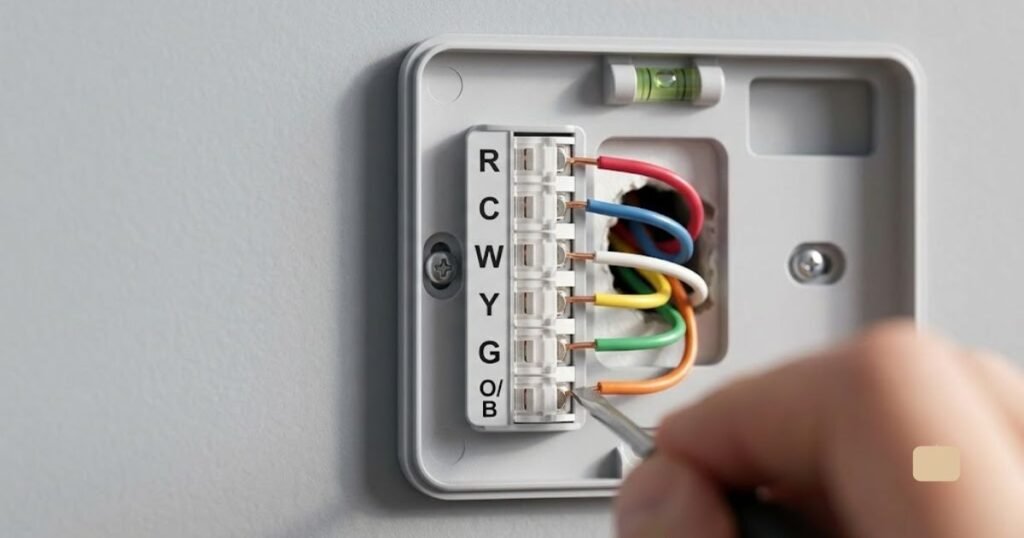
Thermostat Wiring Basics: How Does It Work?
Before touching any wires, it helps to understand what a thermostat actually does. Many homeowners assume the thermostat directly powers their heating and cooling equipment. In reality, a thermostat is simply an automated switch board that sends low-voltage signals to your HVAC equipment.
The 24-Volt Control Circuit
Your home’s furnace, boiler, or air handler contains a small transformer that steps down your home’s line voltage (120V or 240V) to a safe 24 volts AC (24VAC). This low-voltage circuit powers the thermostat’s internal electronics and energizes small relays inside your furnace, air conditioner, or heat pump.
When the room temperature drops below your target setting, the thermostat closes an internal switch, sending a 24V signal down a specific wire to turn on the heat. When the room cools back down to your desired setpoint, the switch opens, breaking the circuit and shutting the system off.
System-Specific Wiring
Because HVAC systems come in many configurations: gas furnaces, electric air handlers, central air conditioners, heat pumps, and multi-stage systems there is no universal wiring layout. A simple heat-only system might use just two wires, while a multi-stage heat pump with backup electric heat can easily require seven or eight. Always reference the specific installation manuals for both your thermostat and your HVAC equipment.

READ MORE: Step-by-Step DIY Smart Thermostat Installation Guide
Thermostat Wire Colors and Terminal Letters Explained
| Terminal | Typical Wire Color | What It Usually Does |
| R / Rh / Rc | Red | 24V power from the transformer |
| C | Blue or black, often | Common wire / 24V return path |
| W / W1 | White, often | First-stage heating |
| W2 | Brown or other | Second-stage heat or auxiliary heat |
| Y / Y1 | Yellow, often | Compressor / cooling |
| Y2 | Varies | Second-stage cooling |
| G | Green, often | Indoor blower fan |
| O / B | Orange or other | Heat pump reversing valve |
| AUX / E | Varies | Auxiliary / emergency heat |
| L / A | Varies | System status or fault signal |
That table is a helpful starting point, but treat it as a convention rather than a rulebook. The person who wired your system may not have used standard colors at all, maybe there was only white wire in the spool that day, or a previous owner did a DIY repair with whatever was on hand.
Manufacturer documentation is consistent on this point: wires should be identified by the terminal they’re connected to, not by their color. A blue wire is commonly used for the C terminal, but it isn’t guaranteed plenty of systems use black, brown, or something else for common. The terminal letter is the only piece of information you should really trust, which is why the single most useful thing you can do before touching any wiring is photograph the existing connections at both the thermostat and the furnace or air handler’s control board.
READ MORE: Best Honeywell Thermostat Models: Buyer’s Guide & Comparison
What Does Each Thermostat Wire Do?
Understanding the precise function of each terminal makes reading thermostat wiring diagrams straightforward. Here is a practical breakdown of how each wire operates within your control system.
1. R Wire (24V Power)
The R terminal supplies 24-volt AC power directly from the HVAC transformer to the thermostat.
- R: General power terminal.
- Rc: Dedicated power for cooling.
- Rh: Dedicated power for heating.
In most modern residential setups using a single transformer for both heating and cooling, a jumper wire or internal switch connects Rc and Rh together. If your home has separate systems such as an oil furnace for heat and a completely independent central AC unit you will have two separate power wires: one in Rh and one in Rc (with the jumper removed).
2. C Wire (Common Wire)
The C wire (Common) completes the 24V electrical circuit back to the HVAC transformer. Standard manual or battery-operated thermostats don’t require a C-wire because they simply bridge mechanical contacts or rely on internal AA batteries.
Smart thermostats (like Nest, Ecobee, or Honeywell Home models) feature backlit displays, Wi-Fi radios, and advanced processors. These features require continuous electrical power. The C-wire provides the return path that allows electricity to flow constantly to power these internal components without draining batteries or cycling equipment unexpectedly.
3. W Wire (Heating)
The W terminal controls your home’s heating system. When the thermostat calls for heat, it routes 24V power from the R terminal out through the W wire. This signals your gas valve, oil burner, or electric heating coils to turn on. Multi-stage heating systems add a W2 terminal to control a second, higher-output heating stage.
4. Y Wire (Cooling)
The Y terminal controls your central air conditioner’s compressor. When you set your thermostat to “Cool” and the room warms up, the thermostat routes power from R to Y. In standard split air conditioning systems, this energizes both the outside condenser unit and the indoor cooling circuitry. Systems with two-stage cooling use Y1 for low-stage cooling and Y2 for high-stage cooling.
5. G Wire (Indoor Fan)
The G terminal activates your air handler or furnace blower fan. When you switch your thermostat fan setting from “Auto” to “ON,” the thermostat energizes the G wire, turning on the indoor fan independently of the heating or cooling equipment. This helps circulate filtered air throughout your home even when the system isn’t actively heating or cooling.
6. O/B Wire (Heat Pump Reversing Valve)
The O/B terminal is unique to heat pump systems. Unlike standard AC units, heat pumps can reverse the flow of refrigerant to provide both heating and cooling from the same outdoor unit. The O/B wire controls an internal reversing valve that dictates which direction the refrigerant flows.
- O Configuration: Reversing valve energizes in Cooling mode (standard on systems like Trane, Carrier, and Lennox).
- B Configuration: Reversing valve energizes in Heating mode (common on Rheem and Ruud units).
7. AUX and E Wires (Auxiliary and Emergency Heat)
Heat pumps lose efficiency when outdoor temperatures drop below freezing. To keep up with heat loss, heat pump systems incorporate supplementary heating elements (usually electric resistance heat coils inside the indoor air handler).
- AUX (Auxiliary Heat): Turns on automatically when the heat pump alone cannot satisfy the set temperature.
- E (Emergency Heat): Switches off the outdoor compressor entirely and forces the system to run exclusively on resistance heat strip coils (used if the outdoor compressor freezes or fails).
In many modern thermostats, the AUX and E terminals are combined or configured digitally during setup.
8. Y2, W2, and Advanced Terminals
Higher-efficiency HVAC systems use multi-stage operation:
- W2 / Y2: Control the second stage of heating and cooling for increased comfort and efficiency.
- ACC / DEHUM / HUM: Specialized terminals found on premium smart thermostats used to directly control whole-house humidifiers, dehumidifiers, or powered fresh air dampers.

READ MORE: How to Test a Water Heater Thermostat
Thermostat Wiring Diagrams Explained
No single diagram applies to every home. Your exact wiring depends entirely on the equipment installed. That said, most residential systems fall into a handful of familiar wire-count patterns.
2-Wire Thermostat Wiring
Typically found on heat-only systems, like a simple gas furnace or a boiler with no central air conditioning. You’ll usually see just R and W, since there’s no fan control, no cooling, and often no C-wire on equipment this basic.
3-Wire Thermostat Wiring
Three-wire setups vary more than most, so don’t assume the same three letters every time. A common example is R, W, and G on a heat-only system with a separately controlled fan, but the configuration always depends on what the equipment supports.
4-Wire Thermostat Wiring
A frequent basic setup for heating and cooling without a dedicated common wire: R, W, Y, and G. This covers heat, cooling, and fan control, but it can run into limitations if you upgrade to a smart model that wants continuous power.
5-Wire Thermostat Wiring
This is the configuration most homeowners with central heat and air conditioning will recognize: R, C, W, Y, and G. It’s often called the “standard” setup because it covers power, common, heat, cooling, and fan in one bundle and it’s the wiring most smart thermostats are designed around.
6-Wire Thermostat Wiring
Add a sixth wire and you’re usually looking at either a heat pump (R, C, Y, G, O/B, plus one more) or a conventional system with a second stage of heating or cooling (W2 or Y2 added to the standard five).
7-Wire and 8-Wire Thermostat Wiring
Multi-stage heating and cooling, dual-fuel setups (pairing a heat pump with a gas furnace as backup), auxiliary or emergency heat, or add-ons like a humidifier often need seven or eight wires so the thermostat can control every component. These are exactly the setups where matching terminal labels, not colors, becomes essential.
Conventional HVAC Thermostat Wiring Diagram
A typical furnace-and-central-air setup connects like this:
R → R
C → C
Y → Y
G → G
W → W
R delivers 24-volt power to the thermostat. C gives it a continuous return path. Y calls the outdoor compressor for cooling. G runs the indoor fan. W tells the furnace to start heating. Wired this way, the thermostat can independently call heat, cooling, or fan-only operation.
This is a common example, not a universal diagram; some furnaces separate Rh and Rc, some skip the C-wire entirely, and multi-stage equipment adds extra terminals on top of this base pattern. Always confirm against your own equipment’s wiring diagram before assuming a match.

READ MORE: Best ecobee Smart Thermostat Review: Essential vs Enhanced vs Premium
Heat Pump Thermostat Wiring Diagram
Heat pump wiring looks similar at first glance but works differently under the hood, since the same equipment handles both heating and cooling through a reversing valve rather than a separate furnace and AC unit.
R → R
C → C
Y → Y
G → G
O/B → O/B
Here, Y still calls the compressor, but the compressor runs in both heating and cooling seasons; it’s the O/B terminal controlling the reversing valve that determines which direction it’s operating in. Auxiliary or emergency heat, when present, comes in through separate AUX or E terminals rather than a simple W call like a furnace uses.
Whether your system uses O or B and what temperature it flows the valve in for which mode depends entirely on the equipment manufacturer, not on wire color. Don’t guess at O versus B based on which wire happens to be orange; check the installer or equipment settings, because getting this wrong is one of the most common reasons a heat pump blows cold air in winter or warm air in summer.

What Is a C-Wire and Do You Need One?
The C-wire is one of the most-searched thermostat topics for a good reason: it’s the difference-maker for smart thermostat installs. It completes the 24-volt circuit and gives the thermostat continuous power, rather than only power drawn briefly whenever heating or cooling is called for.
Older mechanical and battery-powered digital thermostats generally didn’t need one they got by on batteries or brief “power stealing” from the heating/cooling circuit itself. Smart thermostats with color touchscreens, Wi-Fi radios, and always-on sensors typically draw more continuous current, which is why many manufacturers recommend or require a C-wire connection.
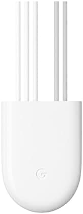
That doesn’t rule out a smart thermostat if your walls only have four wires, though. Some models run on power-stealing techniques without a dedicated C-wire, and C-wire adapters or power extender kits exist to add continuous power at the furnace side without running new wire through the walls. Compatibility varies by brand and system, so check the specific model’s requirements and your existing wire count before buying.
READ MORE: Best Energy Star Smart Thermostats: Reviews, Comparison, and Buying Guide
Can You Install a Smart Thermostat With Existing Wiring?
Before buying a smart thermostat, walk through these checks:
- What’s your existing thermostat model, and what’s it wired to today?
- Which terminals are currently connected, including any capped-off spares?
- What type of HVAC system do you have (furnace/AC, heat pump, boiler, electric, dual-fuel)?
- How many wires actually run to the thermostat location?
- Is there a C-wire present, connected or not?
- Does the new thermostat’s compatibility checker confirm it works with your system?
- What does the manufacturer’s installation guide say about your specific wire count?
If your walls don’t have a C-wire, a smart thermostat may still work using a manufacturer-approved power extender kit, which borrows an otherwise-unused wire to establish continuous power at the furnace end. Skipping this check is how homeowners end up with a thermostat that reboots randomly or can’t hold a Wi-Fi connection.
How to Read an HVAC Thermostat Wiring Diagram
Step 1: Identify the HVAC system. Furnace and central AC, heat pump, boiler, electric baseboard, dual-fuel, multi-stage, or zoned the type determines which diagram actually applies to your house.
Step 2: Photograph the existing thermostat wiring before touching anything.
Step 3: Record the terminal letters each wire is connected to, not just the colors.
Step 4: Check the HVAC control board. Its terminal labels are often more reliable and detailed than what’s printed on the thermostat’s wall plate.
Step 5: Compare both diagrams — the existing thermostat’s and the new one’s terminal by terminal.
Step 6: Verify thermostat compatibility against your specific equipment before installing.
Step 7: Only then consider changing any wiring, and only per the manufacturer’s current instructions.
READ MORE: Is a Google Nest Thermostat Worth It? Review, Comparison & Buyer Guide
How to Replace a Thermostat Without Mixing Up the Wires
- Turn off power to the HVAC system at the breaker or service switch.
- Confirm the system is actually powered down before touching wires.
- Photograph the existing connections at both the thermostat and the control board.
- Label each wire with tape or a marker as you disconnect it.
- Remove the old thermostat from the wall.
- Compare the old terminal labels against the new thermostat’s terminal layout.
- Connect each wire according to the new thermostat’s installation instructions matching terminal letters, not colors.
- Check that no bare wire ends are loose or touching each other inside the wall plate.
- Restore power to the system.
- Test heating, cooling, and fan operation before considering the job done.
Even on a low-voltage circuit, wiring mistakes aren’t harmless. A crossed connection can trip a control-board fuse, damage a transformer, or cause equipment to run in a way it shouldn’t. Working carefully and methodically matters here just as much as anywhere else in your electrical system.
Common Thermostat Wiring Mistakes Homeowners Make
- Assuming wire color is always correct instead of checking the terminal
- Forgetting to shut off power before disconnecting wires
- Mixing up R, Rh, and Rc on systems with two transformers
- Misidentifying which wire is actually the C-wire
- Wiring a heat pump the same way as a conventional furnace-and-AC system
- Guessing at O versus B instead of confirming the correct setting
- Overlooking the auxiliary heat connection on a heat pump system
- Leaving bare copper exposed or touching another terminal
- Applying a wiring diagram meant for a different type of HVAC system
- Assuming every thermostat brand uses identical terminal names
- Skipping a check of the HVAC control board’s own labels
- Installing a smart thermostat without confirming it’s compatible first
None of these require a degree in electrical engineering to avoid — they mostly come down to going slow, checking the terminal, and not assuming your neighbor’s setup matches yours.
Thermostat Wiring Problems and Troubleshooting
Thermostat has no power. Could be a missing or incorrect C-wire connection, a blown low-voltage fuse on the control board, a tripped breaker, a loose wire, or a transformer issue.
AC won’t turn on. Check whether Y, R, and C connections are secure; if wiring looks fine, the issue may be at the control board or the outdoor unit itself.
Furnace won’t turn on. Often traced to the W or R connection, or a control board fault — beyond a basic wire check, this typically calls for a technician.
Fan won’t run. Usually a G-wire connection issue, or a thermostat setting that isn’t actually calling for fan operation.
Heat pump blows cool air in heating mode. A frequent sign of an O/B configuration mismatch between the thermostat setting and what the equipment expects.
Smart thermostat keeps restarting. Commonly a power supply issue — often tied to a missing or improperly wired C-wire, or a compatibility gap with the existing system.
Simple checks a loose wire, a tripped breaker, a suspect terminal connection are reasonable for most homeowners. Anything involving the control board itself, a repeatedly blown fuse, or unpredictable equipment behavior is a sign to bring in a professional.
READ MORE: Sensi Smart Thermostat Review & Comparison
When Should You Call an HVAC Professional?
Consider bringing in a technician when:
- The existing wiring doesn’t match either thermostat’s diagram
- Your system uses multiple transformers
- You have a dual-fuel system pairing a heat pump with a furnace
- Your home has a complex zoned HVAC setup
- You can’t confidently identify what type of HVAC system you have
- The control board itself shows damaged or frayed wiring
- A fuse keeps blowing no matter what you check
- The thermostat causes heating or cooling behavior you didn’t expect
- You’re simply not comfortable working around HVAC equipment
That said, most basic thermostat swaps, same system type, same wire count, straightforward terminal matching are well within reach for a careful homeowner. Professional help is about matching the job’s complexity to your comfort level, not a requirement for every wiring job.
Thermostat Wiring Diagram Quick Reference
| System Type | Common Terminals | Typical Use |
| Heat only | R, W | Furnace or boiler heat |
| Heat + AC | R, C, W, Y, G | Conventional HVAC |
| Heat pump | R, C, Y, G, O/B | Heating and cooling |
| Heat pump + auxiliary heat | R, C, Y, G, O/B, AUX | Heat pump with electric backup heat |
| Multi-stage HVAC | Adds W2 / Y2 | Multiple heating or cooling stages |
This is a general reference, not a substitute for your equipment’s specific wiring diagram.
Frequently Asked Questions
What do the wires on a thermostat mean?
Each wire connects to a labeled terminal: R carries 24-volt power, C is the common wire for continuous power, W calls for heat, Y calls the compressor for cooling, G runs the indoor fan, and O/B controls a heat pump’s reversing valve.
What color is the C-wire on a thermostat?
Blue is common, but there’s no guaranteed industry-wide color standard — a C-wire could just as easily be black or another color. The terminal label matters far more than the color.
Can I install a thermostat without a C-wire?
Sometimes. Some thermostats run without one using power-stealing techniques, while others need a C-wire adapter or power extender kit. Check the specific model’s compatibility requirements before assuming either way.
How do I wire a thermostat for a heat pump?
A typical setup uses R, C, Y, G, and O/B, with AUX or E added for backup heat. Exact terminal use, and whether the system relies on O or B, varies by equipment manufacturer.
What happens if thermostat wires are connected incorrectly?
Depending on the mistake, the system may not operate, run heating when you expect cooling (or vice versa), blow a low-voltage fuse, or in some cases damage the control board — which is why matching terminal labels carefully matters, even on a “simple” low-voltage circuit.


Pingback: Ecobee vs Honeywell vs Nest: Which Smart Thermostat Is Best? - Plumbing Guider